
English 
No.36, Fada Road, Taicang, Jiangsu
Views: 0 Author: Site Editor Publish Time: 2026-08-17 Origin: Site


Upgrading or installing an automated RV Poptop Roof shifts the primary failure risk from human fatigue to mechanical reliability. You no longer have to push heavy fiberglass panels upward against stiff gas struts. A motorized system handles the heavy lifting for you. However, a poorly regulated lifting system does not just fail quietly; it can cause severe torsional damage to the roof frame or leave users stranded with an un-retractable top. The stakes are high when you rely on electrical components in remote locations.
Evaluating an RV Poptop Roof Control System requires looking past basic lift capacities and focusing on the underlying software and hardware failsafes. Raw motor power means nothing without intelligent regulation. Buyers and upfitters must specifically examine actuator synchronization, variable height control (commonly known as the hover function), and mechanical override capabilities. These three pillars ensure your automated camper roof acts as a reliable shelter rather than a costly structural liability.
Synchronization prevents structural damage: Hall effect sensors and dual-motor controllers are mandatory to prevent twisting and binding in the vertical lifting mechanism.
Hover functions offer climate utility: Advanced control systems allow for partial deployment, enabling dynamic ventilation and wind-resistance management.
Manual override is a non-negotiable failsafe: Every electric RV poptop roof must feature a verified mechanical bypass to ensure the roof can be lowered during complete 12V power loss or actuator failure.
System integration matters: IP ratings, parasitic power draw, and compatibility with existing 12V/24V electrical banks differentiate premium systems from aftermarket workarounds.
Transitioning from manual gas struts to electric linear actuators introduces the immediate risk of uneven lifting loads. Camper roofs rarely maintain perfectly balanced weight distribution. You might mount a heavy solar panel array favoring the driver's side. You might store recovery tracks on a rear roof rack. Sometimes, heavy rain soaks the canvas unevenly. This uneven weight distribution causes asynchronous lifting when independent motors push upward. The heavier side naturally encounters more resistance, causing its motor to lag behind the lighter, faster side.
The cost of this mechanical failure is severe. Without a dedicated control module regulating motor speeds, minor variances between actuators compound rapidly over a typical 30-inch stroke. A speed difference of just three millimeters per second translates into massive structural imbalance at full extension. This twisting motion leads directly to frame warping, torn waterproof canvas, or shattered fiberglass shells. Mechanical binding destroys weather seals and snaps mounting brackets.
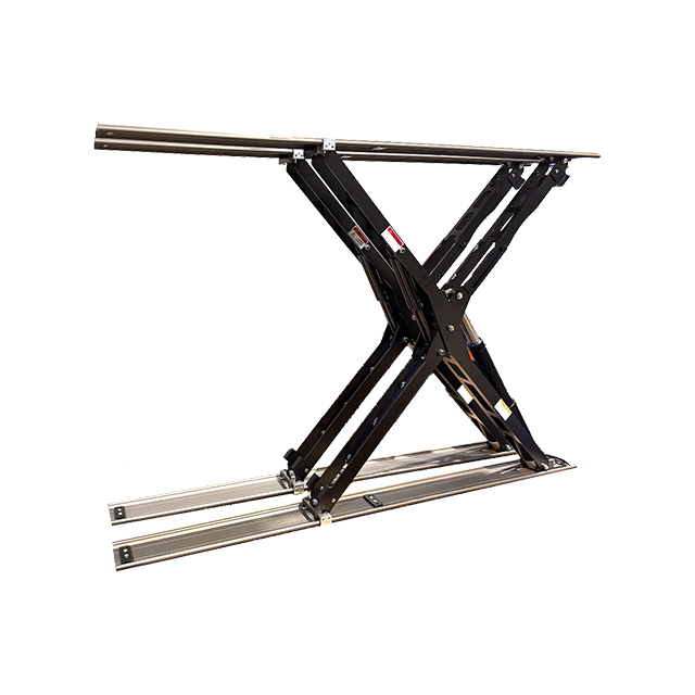
To prevent these disasters, a viable Vertical Lifting Mechanism must meet specific baseline success criteria. It must communicate continuously between all lift points. The onboard computer reads resistance and automatically adjusts voltage to individual motors. It slows down the fast side and boosts power to the slow side. This dynamic micro-adjustment maintains a perfectly level ascent and descent under any load configuration.
Basic linear actuators push and pull blindly. They cannot inherently sense their spatial position. This highlights the absolute necessity of integrating Hall Effect sensors or optical encoders inside the linear actuator chassis. As the internal motor spins, a magnetic ring passes the Hall effect sensor. This interaction generates distinct electrical pulses. The main control board counts these pulses to track the exact millimeter position of each lift point in real-time. It acts as a highly precise digital measuring tape for the motor stroke.
Implementation reality presents complex challenges. A smart synchronization system constantly manages load disparities. Imagine parking your rig on uneven terrain. One side of the frame leans heavily, altering the geometry of the lift. Alternatively, you might deploy a heavy awning attached to one side of the pop-top edge. The pulse-counting controller recognizes the lagging actuator immediately. It throttles voltage to the opposing motor, forcing it to wait until the loaded motor catches up.
When evaluating hardware, look for concrete evidence of trust and reliability. Premium controllers feature automatic shut-off triggers. If pulse counts drift beyond a safe threshold, the entire sequence halts instantly. Typically, engineers set this variance limit between 3 and 5 millimeters. If the system detects a 6-millimeter drift, it cuts power and flashes an error code. This micro-level monitoring prevents catastrophic binding. It protects the structural integrity of the camper by refusing to twist the fiberglass beyond safe tolerances.
Basic systems only recognize two states: fully open or fully closed. Advanced controllers introduce the "Hover" or memory-positioning function. This feature-to-outcome capability allows users to program intermediate stop points. You gain precise control over the interior volume and exterior profile of your camper. This flexibility transforms how you adapt to changing environmental conditions on the road.
Consider these primary use-case scenarios:
High Wind Mitigation: High winds turn a fully extended pop-top into a massive sail. Lowering the roof profile by 50 percent drastically reduces wind load. You maintain basic cross-ventilation while protecting the structural hinges from gale-force gusts.
Stealth Camping: Urban boondocking often requires discretion. Pushing the roof up just a few inches creates minimal clearance for interior airflow. It regulates internal temperatures without blatantly advertising an open pop-top to passersby.
Cold Weather Insulation: Trapping heat in winter requires minimizing interior air volume. A partial lift gives you just enough headroom to sleep comfortably while reducing the cubic footage your diesel heater must warm.
Deploying this feature demands specific technical requirements. You cannot achieve safe partial deployment using standard rocker switches and guesswork. The hover function requires control modules equipped with programmable limit switches or non-volatile memory. Non-volatile memory is crucial. It ensures the computer retains your preset height preferences even after you disconnect the main 12V battery bank for winter storage.
Drawing on common community complaints across VW California or Snowy River owner forums reveals a deep-seated buyer fear. Owners constantly address the anxiety of getting stuck with an elevated roof in a remote location. Actuators rely on 12V power, wiring harnesses, and internal gears. If any single component fails while you camp miles off-grid, you face a massive problem. You cannot drive a vehicle safely at highway speeds with the roof popped.
Understanding the difference between mechanical and electrical overrides helps buyers prepare for emergencies.
Override Type | Mechanism Description | Primary Use Case | Reliability Level |
|---|---|---|---|
Electrical Failsafe | Fused bypass lines jumping the control board. | Dead control module, functional motors. | Moderate (Relies on motor health) |
Quick-Release Pins | Physical pins connecting the actuator to the frame. | Seized motor gears or total power failure. | Extremely High (Gold Standard) |
Hex-Crank Gears | Manual socket interface on the motor chassis. | Loss of 12V power requiring manual cranking. | High (Requires physical effort) |
Electrical failsafes usually involve fused bypass lines. These lines allow you to jump a dead controller directly from a portable lithium jump-pack. You apply 12V power directly to the motor leads. This strategy works perfectly if the computer board dies but the linear actuators remain functional.
Mechanical overrides represent the gold standard of safety. Linear actuators utilize internal worm gears. If a motor burns out, that worm gear locks solidly in place. Human weight cannot physically push down a locked actuator. Every electric system must feature quick-release pins, unbolting mechanisms, or manual hex-crank gears built into the actuator chassis. These devices physically disengage the motor drive from the roof.
Many aftermarket retrofits present a severe implementation risk. Installers sometimes bolt linear actuators directly to the frame without integrating a quick-release bracket. This creates a severe safety hazard. If the motor seizes, you cannot lower the roof without unbolting the entire assembly using power tools. A proper system always includes a tool-free mechanical bypass.
Choosing the right hardware requires a strict decision framework. Do not base your decision solely on the aesthetic appeal of a touchscreen remote. You must evaluate the raw specifications protecting your investment.
Load Rating vs. Actuator Spec: Always apply the 1.5x to 2x rule of thumb. If your maximum loaded roof weighs 200 pounds, spec the combined lifting capacity of your actuators at 300 to 400 pounds. This overhead prevents motor burnout when lifting on inclines or fighting strong headwinds.
Environmental Protection: Roof mechanisms live outside. Require IP66 or IP67 ratings for external actuators. IP66 withstands heavy pressure washing, while IP67 survives temporary submersion. Furthermore, demand a weatherproof housing for any externally mounted control module.
Power Consumption: Evaluate the parasitic draw of the control board when resting in standby mode. High-drain modules pull constant amperage while waiting for a remote signal. This silent drain can kill a house battery during off-season storage. Look for modules boasting sub-10mA standby currents.
System Scalability: Determine how the system interacts with your broader camper build. Can it integrate with standard RV multiplex screens using CAN bus protocols? Alternatively, does it rely entirely on a proprietary, easily lost RF remote? Integrated systems offer much better long-term reliability.
Inspecting these technical details separates premium, purpose-built lifting systems from cheap industrial actuators hastily bolted to a camper van. The control board must act as an intelligent intermediary between your battery and the heavy roof above your head.
An effective RV poptop roof management setup successfully balances brute lifting force with digital precision and analog failsafes. Moving away from manual gas struts enhances user comfort, but it demands rigorous engineering to prevent torsional frame damage. Hall effect synchronization ensures perfectly level movement, while hover features grant you unprecedented control over ventilation and weather management.
Before purchasing a system or finalizing an upfitter contract, take specific action steps. Physically trace out the manual override process. Ask the installer to demonstrate exactly how to drop the roof without battery power. Finally, verify the presence of Hall effect synchronization on the official spec sheet. Ensuring these safeguards exist guarantees your automated roof enhances your off-grid experience rather than compromising it.
A: Only if your system is equipped with a mechanical manual override, such as quick-release pins or a manual crank interface. Standard linear actuators utilize worm gears that lock in place when powered down. They cannot be back-driven by human force. You must physically disconnect the actuator from the roof frame to lower or lift it manually.
A: This usually indicates a lack of a synchronized control system. Uneven weight on the roof, such as solar panels, or differing internal motor friction causes significant speed variations. Motors will lift unevenly unless they are actively regulated by a multi-channel controller reading Hall effect sensors to balance the voltage.
A: Yes, systems featuring a "Hover" function use electronic braking and memory positioning to safely hold the roof at partial heights. The internal worm gears prevent the roof from slipping downward, holding the weight securely without causing mechanical drift, even under high wind conditions.


